

521 Series Sealed Front Mount Panel Connector
521 Series Sealed Front Mount Panel Connector
SKU:HIG-478812
Enhanced safety with recessed contacts and spring finger grounding in a 25 kVDC front mount panel connector.
Regular price
$59.99
Regular price
Sale price
$59.99
Unit price
per
Initiate Order

521 Series Sealed Front Mount Panel Connector
$59.99
Quantity: 1
Claim Your Seller Account
521 Series Sealed Front Mount Panel Connector
$59.99
Quantity: 1
Delivery via Maden
Expect your order to arrive on time.
Secure Payments
All orders are processed through a secure, PCI-compliant checkout.
The 521 Series Sealed Front Mount Panel Connector is a high voltage connector designed for maximum safety in high-risk environments. With recessed contacts that minimize electrical shock risk, this connector features a spring finger grounding mechanism to ensure a reliable ground circuit before engaging the center contact, further enhancing safety measures. Operating between -40 to 85°C, this connector boasts a voltage rating of 25 kVDC at 70,000 ft and a test voltage of 41 kVDC at the same altitude. With a bayonet coupling style, crimp braid termination, and sealed receptacle for added protection, this connector meets stringent industry standards for both consumer and institutional buyers.
Ready to Grow Without Cash Flow Constraints?


Product Specifications
Cable Preparation 0
CLICK HERE FOR A PHOTOGRAPHIC "HOW TO" Series 521 (Sea Level version P/N 167-3516 and 167-3561-1) Series 521 (Reduced Pressure version P/N 167-4534 and 167-4534-1) Step 1 Cut cable to length, clean and square. Strip outer jacket to dimension shown. Trim exposed braid to dimension. Strip inner insulation to dimension and hot tin dip core. No nicked or severed strands allowed during stripping. Step 2 Slip cable seal over center conductor. Slide contact over inner conductor. Place in fixture to apply compression to the cable seal and maintain pressure until completion of the soldering process. Solder contact into place through hole using SN60 solder in accordance with J-STD- 006. Completed solder joint must have a continuous fillet of solder between the inner conductor and the contact. The solder in the feed hole must be flush or below flush and free of pinholes. Step 3 Slip boot and crimp sleeve over cable. Flair braid slightly by moving inner insulation in a circular motion. Coat inner insulation and cable seal liberally with fluorsilicone grease. Step 4 Insert prepared cable into the connector carefully. Do not pinch or otherwise damage the cable seal. Guide braid smoothly over the crimp area of the connector until the contact shoulder butts against the insulator (see âXâ). Slide the crimp sleeve into position, trim excess braid, and crimp using Thomas & Betts crimp tool No. WT-540 with Die No. 5456. (NOTE: this Die Number supercedes the one called out in our printed catalogs). Measure contact depth before and after crimping. Make sure braid does not extend beyond the end of the crimp sleeve. Install interface seal with fluorosilicone grease applied on the back face of the seal. A 521 series receptacle can be used to guide and push the interface seal in place by mating the connectors. HVID - Plug and Receptacle Assembly Instructions Note: Assembly procedures apply to both plug and receptacle. Only receptacle assembly is shown. Step 1 Cut cable to length, clean and square. Strip cable to dimension shown. No nicked or severed strands allowed during stripping. Hot tin dip exposed wire and remove rosin residue. Solder contact into pace through solder hole. Remove rosin residue. Step 2 Lightly abrade wire insulation in area shown using fine non-metallic abrasive silica paper. Clean with acetone using a lint free tissue or cloth. Air dry for five minutes. Step 3 Apply a light coat of Dow #1204; primer to the surface of the contact in the area shown. Take care to avoid getting primer on the mating surface of the contact. Step 4 Apply a light coat of Dow # 93076-2 adhesive to the primed surface of the contact and the abraded surface of the silicone cable. Note: The adhesive is a two-part adhesive and must be mixed according to the manufacturerâs instructions. Step 5 Clean molded connector body cavity using cleaning procedure of Step 2. Let air dry for five minutes. Insert the cable/contact into the connector body until the contact bottoms out. Remove any adhesive that may have gotten on the conductive surface of the contact. Apply a fillet of adhesive to the cable where it enters the molded cavity. Step 6 Allow assembly to cure undisturbed for at least 24 hours. Download this page as a PDF for best print quality.
Contact Properties Contact Diameter
0.077 in | 1.9 mm
Contact Properties Contact Finish
Gold
Contact Properties Contact Material
Brass
Contact Properties Contact Type
Male
Coupling Nut Properties Bayonet Coupling Nut Diameter
0.750 in | 19 mm
Coupling Nut Properties Bayonet Coupling Nut Finish
Nickel
Coupling Nut Properties Bayonet Coupling Nut Material
Brass
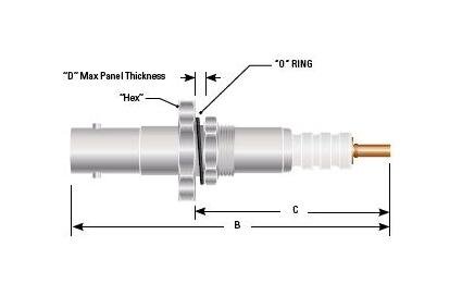
Dimensions B
3.94 in | 100.08 mm
Dimensions C
2.56 in | 65.02 mm
Dimensions D
0.25 in | 6.35 mm
Dimensions Hex
0.93 in | 23.62 mm
Specifications Altitudereduced Pressure Rating
70,000 ft.
Specifications Assembly Type
Receptacle Bag Assembly
Specifications Braid Termination
Crimp
Specifications Coupling Style
Bayonet
Specifications Current Rating
20 A
Specifications Export Classification
TBD
Specifications Mating Compatibility
Mates all series 521 plug cable assemblies
Specifications Maximum Leak Rate Helium
1 X 10 -6 cc/sec
Specifications Operating Temperature
-40 to 85 ºC
Specifications Panel Mounting Style
Front Mount
Specifications Panel Mounting Torque
90 to 95 in-lbs
Specifications Plug Contact Materialfinish
BeCu/Au
Specifications Plug Insulator Material
Plastic
Specifications Pressure Differential Rating
Sealed for 1 ATM
Specifications Receptacle Contact Materialfinish
Brass/Au
Specifications Receptacle Insulator Material
Plastic
Specifications Rohs Compliant
TBD
Specifications Sealed Receptacle
Yes
Specifications Series
521
Specifications Spring Finger Grounding Plug
Yes
Specifications Standardnon Standard
Standard Part
Specifications Test Voltage 70000 Ft
41
Specifications Test Voltage At Sea Level
28 kVDC
Specifications Voltage Rating
25 kVDC
Specifications Wire Insulation
PE
Specifications Wire Type
Shielded