


Advance Lifts Rail Transfer Bridge - 8ft x 18ft - 25000 lbs Capacity
Advance Lifts Rail Transfer Bridge - 8ft x 18ft - 25000 lbs Capacity
SKU:DOC-104d3e
Advanced Rail Transfer Bridge - 8ft x 18ft - 25000 lbs Capacity. ISO 9001:2015 & UL Certified.
Regular price
$12,000.00
Regular price
Sale price
$12,000.00
Unit price
per
Initiate Order

Advance Lifts Rail Transfer Bridge - 8ft x 18ft - 25000 lbs Capacity
$12,000.00
Quantity: 1
Claim Your Seller Account
Advance Lifts Rail Transfer Bridge - 8ft x 18ft - 25000 lbs Capacity
$12,000.00
Quantity: 1
Delivery via Maden
Expect your order to arrive on time.
Secure Payments
All orders are processed through a secure, PCI-compliant checkout.
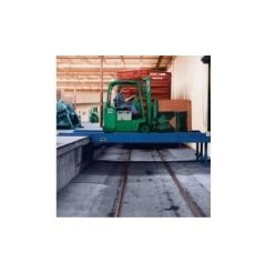
The Advance Lifts Rail Transfer Bridge is a highly durable and versatile solution for spanning railroad tracks from floor to floor or dock to dock. With an impressive width of 8 feet, a clear span length of 18 feet, and a robust 25000-pound capacity, this bridge ensures smooth passage for trains. Designed with industry-leading standards like ISO 9001:2015 certification and Underwriter Laboratories (UL) compliance, it features heavy-duty hydraulic rams, safety tread steel deck, and a self-contained electrical power unit. Ideal for institutional and government buyers seeking reliable and efficient rail transfer solutions.
Ready to Grow Without Cash Flow Constraints?


Product Specifications
Accessories Accessories
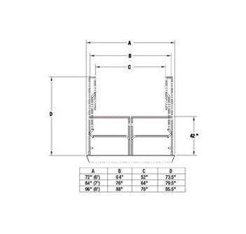
Controls:Fig. 1 - NEMA 4X pushbutton (Standard)Fig. 2 - NEMA 1 wall mount PushbuttonFig. 3 - UP DOWN Key operatedFig. 4 - Push Button With Key LockoutPre-Wired Power Unit:Optional on pit mounted models due to installation considerations, but standard on all portable and top of ground models.Power Unit Covers:Power unit covers are used for weather protection when other shelter is unavailable.Factory Standard Receptacle Charts:Note: Standard voltage for all power units of 1HP or larger is 230/60/3. These units will operate on 208, 220, 230, 240 voltages and if the magnetic overloads are changed, they can be rewired to operate on 440, 460, and 480 voltages also.Oil Immersion Heaters:These devices are popular in colder climates to keep the fluid in the reservoir at a warm temperature. They require a separate 110-volt line and simply screw into the coupling at the bottom of the reservoir.Flashing Light & Audio Alarm:These devices are available as individual items or in combination.Limit Switch:This adjustable limit switch stops the liftâs upward travel at a preset level. To avoid electric lines in the pit, it should only be used where the platform must stop at the same elevation every time.Quick Disconnect:The push button control can be plugged into a receptacle box on the lift. Other variations are available.Paint Colors:Eight standard colors available at no extra charge.Patented Electric Toe Guards:Where personnel protection is desired beyond that required by federal regulations, specify Advance Electric Toe Guards. These stop the downward travel of a platform when an object makes contact with the electric toe guard. Simply pushing the "UP" button on the control station raises the platform so the object can be removed and the system reset. Electric Toe Guards can be installed on any or all of the platform sides. Its hinged actuator projects down and away from the rigid platform toe guard, rather than hanging directly beneath it. Electric Toe Guards can act as an emergency down travel stop switch for anyone within arm's reach of the platform, providing added electronic protection without sacrificing the minimum 8" bevel toe guard mechanical protection required by federal regulations.Night Locks:Night locks are located on the four platform corners. They swivel 360 degrees so they can be positioned over the edge of a concrete dock to mechanically lock the lift in a raised position for security purposes. They are not load supporting devices and are ordered in lieu of hand rails which are not required in a raised concrete loading dock application.Wheel Chock: Wheel chocks are designed to automatically create a barrier for wheels whenever the unit is raised from a fully lowered position.Handrails, Gates & Pipe Stanchions:All loading dock scissor lifts are equipped with handrails along their long sides and safety chains across the ends as standard. However, some applications require gates, pipe stanchions to clip chains to and other special handrail configurations. Let us know your needs.Slip Reducing Decks:Plate manufacturers produce raised pattern plates for better traction which is standard on all dock lifts and an option on all other lifts. We can also embed silica sand in our enamel paint finish on smooth plates, which provides better traction than the embossed plates, but does not hold up to wear as well.Bi-Parting Gates:Our parting gates are available in standard widths of 6', 7', or 8'. See chart for exact dimensions. The gates are held in the upright position by gas air springs. Electrical interlocks are optional.Bi parting gate for 6 ft side with 52" clear widthBi parting gate for 7 ft side with 64" clear widthBi parting gate for 8 ft side with 76" clear widthApproach Ramps:These are standard on "top of ground units" but they are also available for pit mounted units that are not being mounted in pits. There are two types available.Aluminum Bridges & Split Bridges:These options are used to reduce the lifting weight of bridges.Automatic Bridge Activators:To avoid potential injuries, the bridge activator eliminates repeated handling of the hinged bridge. Simply adjust the height of the activator to 3" below the truck bed and lean the bridge against the activator. As the lift raises or lowers, the bridge cams over the activator bar onto or off of the truck bed.Hydraulic Bridge Activator:This option requires no additional electrical lines to the base frame. The control is a separate push button that can be moved to a convenient point on the platform. The cylinder actuator is either mounted under the platform for units with at least 8" lowered heights or on the side of the platform for lower units. Platform working space is never compromised. Truck bed deflection is automatically compensated for in the fully deployed position with a bridge float hydraulic circuit. Solid steel bridges up to 48" long can be used with this option.Walls as Automatic Bridge Activators:In cold climate areas it is popular to position dock lifts inside buildings with a wall in front of the lift to keep cold air out of the building. This requires a bridge long enough to reach over the wall and extend beyond bumpers or bollards into a truck. This can mean a bridge of 36" to 48" in length. The good thing is that a steel wear strip can be installed on the inside of the wall for the bridge to rest against and slide on, so that the wall functions as an automatic bridge activator. The operator never needs to touch the bridge. As the lift is raised, the bridge rides over the top of the wall and reaches into the truck. This same principle can be used without a wall by providing a cross tube or roller on a pipe for the bridge to rest against and over. This is an illustration of a typical wall style bridge activator.
Additional Information Additional Information
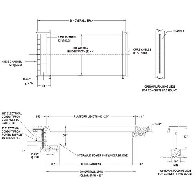
Sometimes due to overhead clearance problems or very long spans, two loading dock bridges are positioned end to end, each hinged on opposing docks so that their traveling ends meet in the middle of the span. In these instances, the traveling ends of the rail transfer bridges are either supported by a concrete pier or each bridge leaf is equipped with automatic folding legs.Note that if a unit is specified that is wide enough for two way traffic, then the bridge capacity specified must exceed the combined weight of the passing traffic and the axle capacity rating must exceed the combined maximum axle weight of the two (2) passing vehicles. Sometimes it is more economical to install two (2) narrower units; each limited to one way traffic.
Architectural Specifications For Rail Transfer Bridges Architect
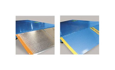
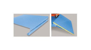
SCOPE: This specification covers Advance Lifts, Inc. Rail Transfer Bridge model number "A".Platform: The bridge deck shall be "B" wide x "D" minus 2-1/2Ⳡlong. The clear span between docks is "C". (Actual platform length is clear span plus 24" for the ram cutout, plus 6Ⳡfor lip cutout, less 1Ⳡclearance at the lip end and 1-1/2" at the ram end.) The bridge shall have a safety tread steel deck and be fabricated from structural steel shapes and forms, which are rigidly welded and reinforced for maximum stability and minimum deflection.Capacity: The bridge shall have a loading capacity of "E" with an axle capacity of "F" at a traffic speed of 3 mph.Travel: The bridge travel shall be a full 90º arc so that none of the bridge mechanism projects beyond the dock when fully raised.Rams: The bridge shall be equipped with "G" heavy-duty double acting hydraulic rams which have chrome plated rods to inhibit rusting. The rams shall also be equipped with steel internal cylinder stops and ceramic wear rings for long life and velocity fuses.Electrical Control: The bridge shall be equipped with two (2) NEMA 1 "dead man" style wall mounted pushbutton control stations (one for each dock) and a UL approved controller assembly consisting of a NEMA 12 control box, magnetic motor starter and a 24 V. control transformer with fused secondary and primary.Power Unit: The electrical power unit shall be self-contained with all components built onto a single oil reservoir. It shall consist of a continuous duty 5HP 230/460V-60HZ-3PH motor, high pressure pump, counter balance valve, oil filters and mild steel reservoir. The overall dimensions shall be approximately 22" x 20" x 21" H.Speed: The bridge shall raise in "I" seconds.Work to be performed by owner: All electrical work, excavation, concrete work, building modifications, pit angle framing, underground piping and embedded items.Work to be performed by Installer: Furnish the hydraulic oil and install the bridge complete less the above exceptions.
Note Note
Please note that we have made bridges up to 100,000 lb. capacity. If you do not see what you need, simply consult the factory.Made in USA.
Specifications Axle Capacity
20000 lb
Specifications Capacity
25000 lb
Specifications Clear Span Length At Docks
18 ft
Specifications Industry Standards
International Organization for Standardization (ISO 9001:2015) Certified | Underwriter Laboratories (UL)
Specifications Overall Span Length
20-1/2 ft
Specifications Rams
3
Specifications Speed
180 seconds
Specifications Weight
8000 lb
Specifications Width
8 ft