
Dual-Channel Transducer Amplifier with Voltage & Current Excitation, 100 kHz Bandwidth
Dual-Channel Transducer Amplifier with Voltage & Current Excitation, 100 kHz Bandwidth
SKU:SIG-f5a14d
Dual-channel amplifier for precise signal conditioning with 100 kHz bandwidth & buffered outputs
Regular price
$799.99
Regular price
Sale price
$799.99
Unit price
per
Initiate Order

Dual-Channel Transducer Amplifier with Voltage & Current Excitation, 100 kHz Bandwidth
$799.99
Quantity: 1
Claim Your Seller Account
Dual-Channel Transducer Amplifier with Voltage & Current Excitation, 100 kHz Bandwidth
$799.99
Quantity: 1
Delivery via Maden
Expect your order to arrive on time.
Secure Payments
All orders are processed through a secure, PCI-compliant checkout.
The Dual-Channel Transducer Amplifier is a versatile signal conditioning module with a 100 kHz bandwidth, ideal for multiple transducer types. It features programmable gains from 1 to 5,000, isolated excitation and input with 300 Volts common mode, and continuous 6-pole low pass filtering. This amplifier offers dual buffered 10 Volt analog outputs, ensuring precise data acquisition and analysis in industrial and research applications.
Ready to Grow Without Cash Flow Constraints?


Product Specifications
Amplifier Analog Output Amplifier
Two ±10 Volt full scale outputs. Accuracy is ±0.05%. Each may be programmed for filtered or wideband response.
Amplifier Bandwidth
100 kHz (-3 dB) for gains 1 to 1,000, 50 kHz (-3 dB) for gains above 1,000. Slew rate is 5 V/µS.
Amplifier Cm Voltage
Common Mode ±300 Volts operating, ±350 Volts without damage.
Amplifier Common Mode
74 dB plus gain in dB to 120 dB for balance input and 110 dB for a 350 Ohm source unbalanced, ±300 Volts, DC to 60Hz.
Amplifier Gain
Programmable from 1 to 5,000 with 0.05% accuracy.
Amplifier Gain Linearity
±0.01% for gains < 1000, ±0.02% gain 1000, and above
Amplifier Gain Stability
±0.01% for 30 days, ±0.005%/ºC.
Amplifier Input Impedance
50 Megohms, shunted by 500 pF DC coupled, 100K Ohms AC coupled.
Amplifier Input Protection
±50 Volts, differential without damage.
Amplifier Input Range
±2 mV to ±10 Volts full scale, DC or AC coupled.
Amplifier Noise 10 Khz
2.0 µV RTI plus 0.3 mV RTO, RMS.
Amplifier Overload Recovery
120 µS to within ±0.1% for a 10 times overload to ±10 Volts.
Amplifier Source Current
±40 nA, ±0.05 nA/ºC.
Amplifier Zero Amplifier
Automatic zero to ±2 µV RTI or ±1.0 mV RTO whichever is greater.
Amplifier Zero Stability
±5 µV RTI, ±1 mV RTO at constant temperature, ±1 µV RTI, ±0.2 mV RTO/ºC.
Bridge Input With Fc1 Features Card Bridge Balance
Automatic by program control. Balance accuracy ±0.05% of range, ±1 mV RTO. Stability ±0.02% for 8 hours, ±0.005%/ºC.
Bridge Input With Fc1 Features Card Bridge Configuration
2 to 10 wire plus shield; input (2), excitation (2), sense (2) and shunt calibration (4). Programmable bridge completion for half bridges and 120 Ohm and 350 Ohm quarter bridges. Other gage resistances by request.
Bridge Modules 0
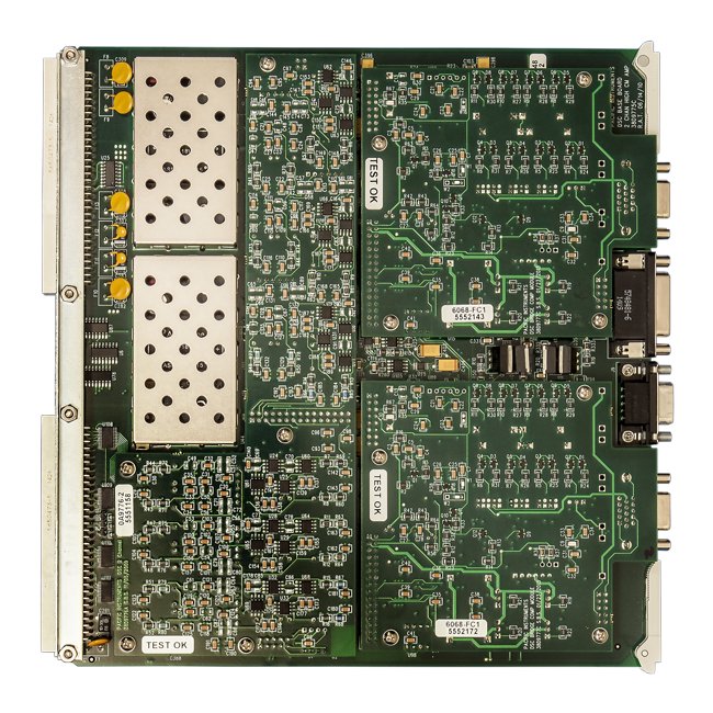
The bridge input is eight or ten-wire shielded accommodating even the most complex transducer wiring schemes. The base board provides both programmable constant voltage with remote sensing and constant current excitation. Programmable completion is provided on the bridge module for quarter, half and full bridge transducers. Automatic bridge balance accommodates large unbalances without limiting dynamic range or loading the transducer output. It can be used to provide voltage offsets in the hundreds of millivolts for non-bridge transducers such as MEMS and variable capacitance.Depending on the function card selected the capability is provided for up to four-steps of bipolar resistive shunt calibration or DAC shunt calibration that provides 4096 calibration steps using a single calibration resistor. The FC1 Bridge Module shown has four steps of unipolar resistance shunt that can be applied to either an external bridge arm or strain gage or to the internal completion resistor. This module may also be used to apply low-level voltage inputs to the instrumentation amplifier on the base board.
Calibration Shunt Calibration
Shunt Calibration based on capability of Installed Features Card. FC1: Four steps of unipolar resistive shunt (8-wire). Four-step bipolar resistive shunt (10-wire) is optionally available. Jumpers provided for 4 and 6-wire connections and for shunting the internal completion resistor.
Calibration Voltage Substitution
Voltage substitution, signal from external calibration source is applied to the amplifier input. Programmable attenuator with steps of 1, 0.1 and 0.01, ±0.02% accuracy. Output of the attenuator is provided for calibration.
Calibration Zero Calibration
Amplifier input disconnected and shorted.
Charge Mode Input With Fc9 Features Card Charge Calibration
Signal from external calibration source applied through a 2,000 pF capacitor to the charge input and calibrated to ±0.1%.
Charge Mode Input With Fc9 Features Card Charge Configuration
Two ranges: 1 mV/pC (high) and 0.1 mV/pC (low).
Charge Mode Input With Fc9 Features Card Charge Gain Range
0.05 mV/pC to 2,500 mV/pC with 0.05% resolution.
Charge Mode Input With Fc9 Features Card Charge Gain Steps
Calibrated gains of 0.1, 0.2, 0.5, 1, 2, 5, 10, 20, 50, 100, 200, 500, 1,000, 2,000, and 5,000 mV/pC with ±0.1% accuracy.
Charge Mode Input With Fc9 Features Card Charge Linearity
0.1% of full scale at 1 kHz.
Charge Mode Input With Fc9 Features Card Charge Stability
±0.005%/ºC.
Current Excitation Transducer Power Current Excitation
Programmable 0.1 mA to 51.2 mA with 1 µA resolution. Calibrated 5 mA steps ±0.1%.
Current Excitation Transducer Power Current Excitation Noise
2 µA or 5 µV peak-to-peak DC to 10 kHz.
Current Excitation Transducer Power Current Excitation Stability
±0.01% or ±2 µA for 30 days. Temperature coefficient is less than ±0.005% or ±1 µA/ºC.
Current Excitation Transducer Power Current Monitor
Excitation voltage or current is read by a program instruction. Accuracy is ±0.2%.
Current Excitation Transducer Power Current Regulation
±0.01% or ±0.1 µA for 10% line change.
Current Excitation Transducer Power Minimum Compliance
0.1 to 20 V
Overview Analog Bandwidth
50 kHz | 100 kHz
Overview Excitationtransducer Power
Current | ICP | Voltage
Voltage Excitation Transducer Power Voltage Excitation
Programmable from 0.1 to 20 Volts with 0.5 mV resolution. Calibrated 2-Volt steps ±0.1%. 50 mA limited to 70 mA maximum.
Voltage Excitation Transducer Power Voltage Excitation Noise
200 µV peak-to-peak, DC to 10 kHz
Voltage Excitation Transducer Power Voltage Excitation Regulatio
Each channel individually regulated. ±0.01% over input voltage range and no-load to full-load.
Voltage Excitation Transducer Power Voltage Excitation Stability
±0.01% for 30 days. Temperature coefficient less than ±0.005%/ºC.
Voltage Excitation Transducer Power Voltage Monitor
Excitation voltage or current is read by a program instruction. Accuracy is ±0.2%.