
High Voltage Female Protective Cover Adapter - Series 311 Cond. 3
High Voltage Female Protective Cover Adapter - Series 311 Cond. 3
SKU:HIG-268c85
Enhanced High Voltage Female Protective Cover Adapter for secure and reliable connections in high-pressure environments
Regular price
$59.99
Regular price
Sale price
$59.99
Unit price
per
Initiate Order

High Voltage Female Protective Cover Adapter - Series 311 Cond. 3
$59.99
Quantity: 1
Claim Your Seller Account
High Voltage Female Protective Cover Adapter - Series 311 Cond. 3
$59.99
Quantity: 1
Delivery via Maden
Expect your order to arrive on time.
Secure Payments
All orders are processed through a secure, PCI-compliant checkout.
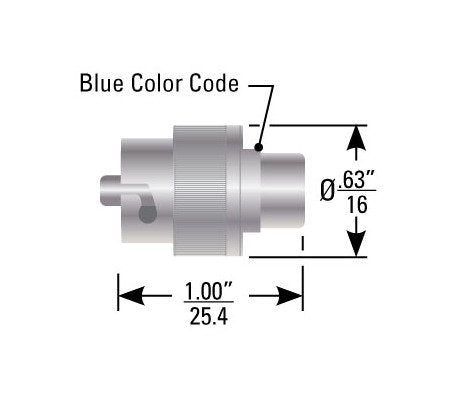
The High Voltage Female Protective Cover Adapter from the 311 Series is designed for operation at reduced pressure, featuring seals for enhanced safety. With a shell-to-shell grounding spring finger shield, hooded female socket, and bayonet coupling for easy polarization, this adapter ensures secure connections. It boasts a current rating of 10 Amp, altitude rating of 70,000 ft., and voltage rating of 15 kVDC, meeting stringent industry standards for reliability and performance.
Ready to Grow Without Cash Flow Constraints?


Product Specifications
Body Properties Coupling Nut Finish
Gold Plated
Body Properties Coupling Nut Material
Brass
Cable Preparation 0
Reynolds Industries Inc. - High Voltage Connectors, High Voltage Cable Assemblies, High Voltage Wire, High Voltage Cable, High Voltage Capacitors _uacct = "UA-425769-1"; urchinTracker(); CLICK HERE FOR A PHOTOGRAPHIC "HOW TO" Series 311 (P/N 167-7624) Step 1 Cut cable to length, clean and square. Slip boot and crimp sleeve over cable. Strip outer jacket to dimension shown. Trim exposed braid to dimension. Trim inner insulation to dimension. No nicked or severed strands allowed. Pot tin dip inner conductor using SN60 solder in accordance with J-STD-006. Remove all flux. Step 2 Solder contact in place through hole using SN60 solder in accordance with J-STD-006. No solder buildup allowed on contact outer diameter. Completed solder joint must have a continuous fillet of solder between the inner conductor and the contact. The solder in the feed hole must be free of pinholes and flush or below flush. Rear of contact shoulder shall be as flush as possible with insulation of cable core, but not to exceed .030". Flair braid by moving cable core in a circular motion. Step 3 Solder contact in place through hole using SN60 solder in accordance with J-STD-006. Completed solder joint must have a continuous fillet of solder between the conductor and the contact. The solder in the feed hole must be free of pinholes and flush or below flush. Rear of contact shoulder shall be as flush as possible with insulation of cable core, but not to exceed .030". Download this page as a PDF for best print quality.
Specifications Altitudereduced Pressure Rating
70,000 ft.
Specifications Assembly Type
Protective Cover
Specifications Bayonet Coupling Nut Finish
Nickel
Specifications Bayonet Coupling Nut Material
Brass
Specifications Coupling Style
Bayonet
Specifications Current Rating
10 Amp
Specifications Export Classification
TBD
Specifications Mating Compatibility
Mates all Series 311 Cond. 3 receptacles and adaptors.
Specifications Operating Temperature
-40 to 85 ºC
Specifications Polarization
Cond. 3
Specifications Rohs Compliant
TBD
Specifications Sealed Receptacle
No
Specifications Series
311
Specifications Standardnon Standard
Non-standard Part
Specifications Test Voltage
TBD
Specifications Voltage Rating
15 kVDC