


HYDAC Hose Break Valve
HYDAC Hose Break Valve
SKU:ACC-7bf17f
Ensure safety during line ruptures with the HYDAC Hose Break Valve. Adjustable flow rates and high durability for critical applications.
Regular price
$69.99
Regular price
Sale price
$69.99
Unit price
per
Initiate Order

HYDAC Hose Break Valve
$69.99
Quantity: 1
Claim Your Seller Account
HYDAC Hose Break Valve
$69.99
Quantity: 1
Delivery via Maden
Expect your order to arrive on time.
Secure Payments
All orders are processed through a secure, PCI-compliant checkout.
The HYDAC Hose Break Valve is designed to eliminate uncontrolled movements in the event of a line rupture, safeguarding both equipment and personnel. This cartridge-type valve features a flat seat design with adjustable closing flow rates, ensuring reliable operation during emergencies. With a durable construction suitable for general purpose hydraulic oil and operating pressures ranging from 10 to 350 bar, this valve meets stringent industrial standards for safety and performance.
Ready to Grow Without Cash Flow Constraints?


Product Specifications
Additional Information 0
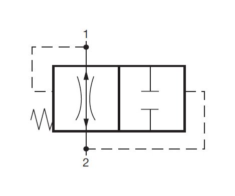
This closing flow rate is adjustable. The valve opens automatically by pressurizing connection1.Depending on the pressure P, the leakage rate through the valve is approximately 0 to 6 in 3 / min. If this is excessive, the valve threads can be sealed and made leak-free.The valves are installed between actuators and possible line breakage points.A cartridge-type valve can be installed into an actuator port.A housing-type valve can be installed close to the actuator or even directly into the actuator itself.
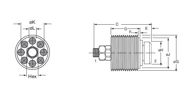
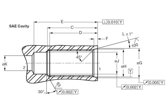
Dimensions Diameter G Housing
0.618 in
Dimensions Diameter G Valve
9/16-18UNF-2B
Dimensions Diameter H Housing
9/16 in.-18UNF-2B
Dimensions Diameter H Valve
0.374 in | 9.5 mm
Dimensions Diameter J Housing
0.435 in
Dimensions Diameter J Valve
0.460 in | 11.7 mm
Dimensions Diameter K Min Housing
0.297 in
Dimensions Diameter K Valve
0.315 in | 8 mm
Dimensions Diameter L Valve
0.098 in | 2.5 mm
Dimensions Dimensions C Valve
0.866 in | 22 mm
Dimensions Dimensions D Valve
0.453 in | 11.5 mm
Dimensions Dimensions E Valve
0.138 in | 3.5 mm
Dimensions Dimensions F Valve
0.13 in | 3 mm
Dimensions Dimension C Housing
1.250 in
Dimensions Dimension D Housing
1.188 in
Dimensions Dimension E Housing
1.56 in
Dimensions Dimension F Housing
0.106 in
Dimensions Dimension Hex Valve
0.197 in | 5 mm
Dimensions Dimension L Housing
12 º
Recommendations 0
Hose break valves, type RBE must only be used to safeguard users in the event of hose breaks. They must not be used as switching valves for repeated closing actions.If closing actions occur during normal operation, the setting of the hose break valve is not suitable for the operating parameters of the system.The hose break valve must be replaced by a new one with a modified setting.In order to prevent hose break valves reacting to flow rate fluctuations inherent in the system, e.g. due to switching of directional valves, the actuating flow rate should be at least 20% above the normal maximum system flow rate. If high viscosity fluctuations occur, the valves must be set to a higher actuating flow rate to ensure trouble-free operation at high viscosity. However, the valves must still react at a low viscosity. Since this range depends largely on the system, whose operational flow rate fluctuations can also depend on viscosity, the appropriate setting for the valve is best determined on site.
Sizing Hose Break Valves 0
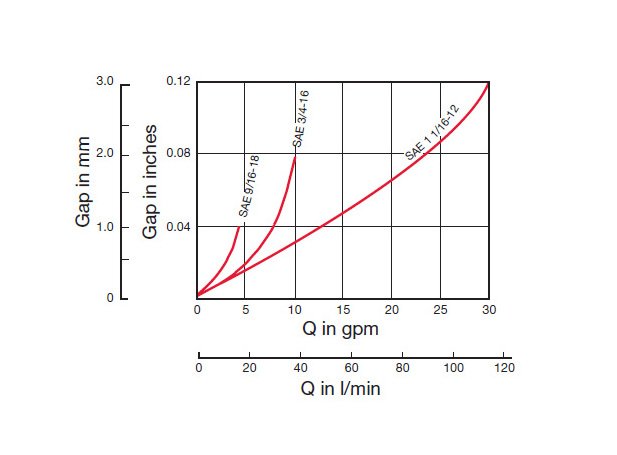
In order for a hose break valve to work properly there must be a difference between the normal operating flow rate (from pump) and the emergency flow rate created by a hose or line break. The emergency flow rate must be significantly higher than the normal operating flow. Why? The hose break valve is designed to only be closed in an emergency situation. These valves should not be cycled (opened and closed) with the system. Cycling the valve and/or excessive vibrations will lead to premature failure of the valve components.How do you determine the emergency flow rate? You must perform a test with the actual system in a hose break simulation. This test should be run with the minimum load on the cylinder/lift to determine the minimum emergency flow rate for the system. To test, break the line open or open a directional valve and allow gravity to pull down the cylinder/lift. The flow rate measured during this test is the emergency flow rate.The hose break closing flow rate setting is adjustable and should be set to close at a flow rate between the normal flow rate and the emergency flow rate. The closing flow rate should be set at least 20% higher than the normal flow rate, and should be set at least 20% below the emergency flow rate.How do you set the closing flow rate for the valve? The gap between the poppet and the valve body is adjustable by means of the lock nut and adjustment nut on the end of the poppet. The larger the gap, the higher the closing flow rate for the valve.
Specifications Bun
EA
Specifications Closing Flow Rate Max
4 gpm | 15 L/min
Specifications Closing Flow Rate Min
1 gpm | 4 L/min
Specifications Connection Size
SAE 9/16-18
Specifications Design
Flat Seat Valve
Specifications Direction Of Flow 1 To 2
Free Flow
Specifications Direction Of Flow 2 To 1
Free Flow; valve automatically closes if flow exceeds preset level
Specifications Division
ACCESSORIES
Specifications End Type
Cartridge Only
Specifications Fluid Temperature
80 ºC | 176 ºF
Specifications Housing Type
Cartridge Only
Specifications Medium
General Purpose Hydraulic Oil
Specifications Model Code Description
RBE-SAE9/16-18-X-15LPM STD. SET
Specifications Operating Pressure Ratings Max
350 bar | 5000 psi
Specifications Operating Pressure Ratings Min
10 bar | 145 psi
Specifications Product
FLOW CONTROL VALVES
Specifications Product Group Family
CARTRIDGE VALVES
Specifications Style
Cartridge