

Large Magnetic Particle Clutch - 0.7 to 95 N·cm Torque Range
Large Magnetic Particle Clutch - 0.7 to 95 N·cm Torque Range
SKU:LAR-bca81a
Precise and versatile large magnetic particle clutch with 0.7 to 95 N·cm Torque Range - ideal for tension control and soft starts.
Regular price
$1,799.99
Regular price
Sale price
$1,799.99
Unit price
per
Initiate Order

Large Magnetic Particle Clutch - 0.7 to 95 N·cm Torque Range
$1,799.99
Quantity: 1
Claim Your Seller Account
Large Magnetic Particle Clutch - 0.7 to 95 N·cm Torque Range
$1,799.99
Quantity: 1
Delivery via Maden
Expect your order to arrive on time.
Secure Payments
All orders are processed through a secure, PCI-compliant checkout.
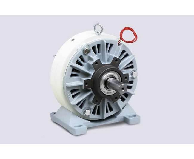
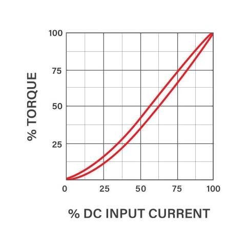
The Large Magnetic Particle Clutch offers a versatile Torque Range from 0.7 to 95 N·cm, suitable for a wide range of applications such as tension control, load simulation, torque limiting, and soft starts. With smooth and repeatable torque delivery, this clutch ensures accurate control independent of speed. Its nearly linear torque vs. current curve makes it ideal for demanding tasks like adjustable tension for rewinding webs. The clutch is engineered by Placid Industries, renowned for reliability and performance.
Ready to Grow Without Cash Flow Constraints?


Product Specifications
Characteristics Characteristics
With no electrical excitation, the input shaft & output shaft freely rotate.With electrical excitation, the output shaft becomes coupled to the input shaft.While the load torque is less than the output torque, the clutch drives without slip.When the load torque is increased, the clutch will slip smoothly at the torque level set by the coil input current.
Determining Proper Clutch Size Determining Proper Clutch Size
Determining Proper Clutch SizeThe proper sized clutch mustâ¦Have sufficient torqueBe able to dissipate the heatNo run above rated speedTorqueFor load simulation, torque limiting and similar applications, torque is already known.For web handling, torque must be calculated. First determine the desired tension in your web (wire, fabric, film etc.).Calculate Torque: Torque (lb-inches) = Tension (lbs) x Roll Diameter (inches) x 0.5Use the Full Roll Diameter for calculating the maximum torque needed. For applications with the web running over a pulley or between nip rollers (pinch rollers), use the pulley diameter as the roll diameter in the formula above. Always be conservative - select the next larger model if the application requires nearly the rated torqueRPM (must be less than the maximum allowable)For load simulation, torque limiting and similar applications, RPM is already known.For web handling, usually linear speed (Web Speed) is known, and RPM must be calculated.Calculate RPM: RPM = 3.8 x WEB SPEED (feet per minute)/ROLL DIAMETER (inches)Use the Full Roll Diameter to determine the slowest speed. Use the Core Diameter (empty spool diameter), to determine the fastest speed. For applications with the web running over a pulley or between nip rollers (pinch rollers), use the pulley diameter as the roll diameter.Slip Heat Dissipation (model must be physically large enough not to overheat)For any application.Calculate Heat Input: HEAT (watts) = TORQUE (lb-inches) x RPM x 0.012For unwinding applications.Calculate Heat Input: HEAT (watts) = WEB TENSION (lbs) x WEB SPEED (feet/minute)/44To minimize heat input in clutch applications, clutch input RPM should only be about 30-40 RPM faster than the fastest required output RPM. Faster slip speeds generate higher heat and wear with no benefit. Select a gearmotor ratio to achieve this.For applications with a large percentage change in roll diameter, use an automatic system to control the gearmotor, so the clutch input shaft is always 30 RPM faster than the output shaft. Mount a sensor on each clutch shaft to measure RPM. Connect to the controller. Program to maintain 30 RPM slip. The controller's 0-10v or 4-20mA output can control a variable speed motor drive. Select a varible speed drive to suit your motor.Duty CycleThe average heat input must be below the brake's heat dissipation rating. If the motion is intermittent, use the average speed for thermal (SLIP) calculations.
How Magnetic Particle Clutches Work How Magnetic Particle Clutch
The output disk/shaft does not touch the rotor. The gap in between is filled with a fine, dry stainless steel powder.The powder is free flowing, until a magnetic field is applied from the stationary coil. The powder particles form chains along the magnetic field lines, linking the disk to the rotor.The torque transmitted from input shaft to the output shaft is proportional to the magnetic field strength, and therefore to the applied D.C. input current.
Specifications Maximum Overhung
175 lb | 780 N
Specifications Maximum Speed
1800 rpm
Specifications Slip Heat Dissipation
300 to 800 W
Specifications Torque Range
0.5 to 70 lb·ft | 0.70 to 95 N·cm
Specifications Weight
87 lb | 39.4 kg
Torque Torque
Is proportional to input current.Is independent of RPM.
Applications Applications
Adjustable tension for rewinding websLoad simulationTorque limitingSoft starts