


Strainsert SPHC Series Hydraulic Cylinder Load Pins
Strainsert SPHC Series Hydraulic Cylinder Load Pins
SKU:LOA-e1b067
Upgrade to precision with Strainsert SPHC Series Hydraulic Load Pins, designed for accurate force measurement in hydraulic systems.
Regular price
$399.99
Regular price
Sale price
$399.99
Unit price
per
Initiate Order

Strainsert SPHC Series Hydraulic Cylinder Load Pins
$399.99
Quantity: 1
Claim Your Seller Account
Strainsert SPHC Series Hydraulic Cylinder Load Pins
$399.99
Quantity: 1
Delivery via Maden
Expect your order to arrive on time.
Secure Payments
All orders are processed through a secure, PCI-compliant checkout.
Experience precision force measurement with the Strainsert SPHC Series Hydraulic Cylinder Load Pins, featuring strain gage transducers designed for accurate load monitoring. Utilizing a double-shear arrangement and sealed strain gages, these pins ensure reliable performance. With a load capacity of 100,000 lbs and full bridge output, these pins offer exceptional non-repeatability and hysteresis. Upgrade your hydraulic system with these load pins for optimal force measurement and efficiency.
Ready to Grow Without Cash Flow Constraints?


Product Specifications
Electrical Specifications Cable
#20(26x34) AWG., rubber insulation, shielded, rubber jacket, 4-Conductor (Standard Cable)
Electrical Specifications Excitation
Red
Electrical Specifications Function
Wire Code
Electrical Specifications Mating Plug
PT06A-10-6S (SR)
Electrical Specifications Receptacle
PTIH-10-6P
Electrical Specifications Signal
Green
Features 0
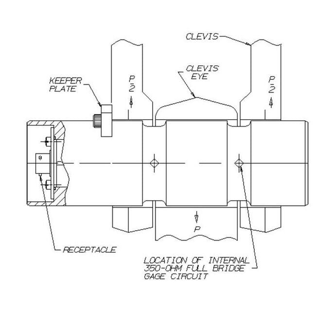
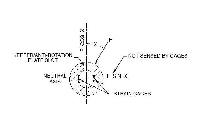
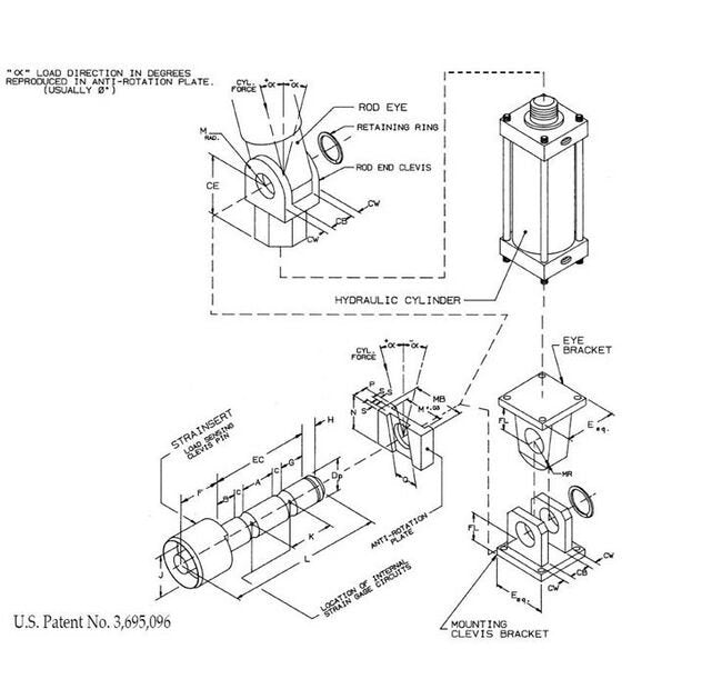
Actuator/Hydraulic Cylinder Load Pins are strain gage transducers developed by Strainsert (U.S. Patent No. 3,695,096). They are manufacured utilizing the internal strain gage process perfected by Strainsert since 1960. We offer precision force measurement by simply replacing existing hydraulic cylinder load pins.The design is a double-shear arrangement. Typically, force P is applied at the center of the pin while 2 equal opposing forces of P/2 are applied at each end. Strain gages are sealed inside a small axial hole and are positioned at the 2 shear locations at the interface between the center eye and pin ends. The strain gages are positioned and oriented with great precision along the neutral plane relative to the specific direction of force.An anti-rotation device is necessary for proper reading and alignment. If a force P is applied to the pin at an angle other than the specified direction, the theoretical bridge output will be offset by a component of the force along the sensitive direction, i.e. P cos X.The four strain gages (two at each shear location) are electrically connected to form a full bridge, the signal from each gage being additive so that the bridge output is proportional to the sum of the forces transmitted by the shear planes of the pin. The circuit typically includes temperature compensation, signal trim (optional), and zero balance resistors terminating in a suitable connector socket or integral cable, and potted with a sealing compound inside the gage hole for enhanced environmental protection.Standard models include detailed calibration data up to 500,000 lbs. Higher capacity calibration data is available at an additional charge. Strainsert factory calibrations are intended to simulate installed conditions, however, it is recommended that an in-place calibration be performed to account for any installation, tolerance, and/or alignment influences affecting sensor measurement.Standard models are typically used in new applications where the designer can develop the specific load pin joint around the standard load pin dimensions, to optimize force measurement performance. In addition, the standard load pin may fit or can be incorporated through the use of bushings or modification of the assembly.
General Information 0
Actuator/Hydraulic Cylinder Load Pins are strain gage transducers developed by Strainsert (U.S. Patent No. 3,695,096). They are manufacured utilizing the internal strain gage process perfected by Strainsert since 1960. We offer precision force measurement by simply replacing existing hydraulic cylinder load pins.The design is a double-shear arrangement. Typically, force P is applied at the center of the pin while 2 equal opposing forces of P/2 are applied at each end. Strain gages are sealed inside a small axial hole and are positioned at the 2 shear locations at the interface between the center eye and pin ends. The strain gages are positioned and oriented with great precision along the neutral plane relative to the specific direction of force.An anti-rotation device is necessary for proper reading and alignment. If a force P is applied to the pin at an angle other than the specified direction, the theoretical bridge output will be offset by a component of the force along the sensitive direction, i.e. P cos X.The four strain gages (two at each shear location) are electrically connected to form a full bridge, the signal from each gage being additive so that the bridge output is proportional to the sum of the forces transmitted by the shear planes of the pin. The circuit typically includes temperature compensation, signal trim (optional), and zero balance resistors terminating in a suitable connector socket or integral cable, and potted with a sealing compound inside the gage hole for enhanced environmental protection.Standard models include detailed calibration data up to 500,000 lbs. Higher capacity calibration data is available at an additional charge. Strainsert factory calibrations are intended to simulate installed conditions, however, it is recommended that an in-place calibration be performed to account for any installation, tolerance, and/or alignment influences affecting sensor measurement.Standard models are typically used in new applications where the designer can develop the specific load pin joint around the standard load pin dimensions, to optimize force measurement performance. In addition, the standard load pin may fit or can be incorporated through the use of bushings or modification of the assembly.
Performance Specs Bridge
Full bridge 350 Ohm (Nominal)
Performance Specs Calibration
CAL5-LO
Performance Specs Excitation
12 V AC (Maximum) | 12 V DC (Maximum)
Performance Specs Hysteresis
±0.50% FS (Nominal)
Performance Specs Non Linearity
±0.50% FS (Nominal)
Performance Specs Non Repeatability
±0.15% FS (Nominal)
Performance Specs Output Signal
2-mV/V (Nominal) | 2-mV/V (Standardized Output)
Performance Specs Overload Without Failure
300% (Minimum)
Performance Specs Overload Without Zero Shift
150%
Performance Specs Service Temp Range
to 150 °F
Performance Specs Temp Effects On Output
0.008% load / °F (Nominal)
Performance Specs Temp Effects On Zero
0.005% FS / °F (Nominal)
Performance Specs Zero Balance
±2% FS (Nominal)
Specifications A Width Of Center Loading Section
2.31 in
Specifications B Width Of Clevis Support Section
1.53 in
Specifications Cb Thickness
3.00 in
Specifications Ce Length
6.75 in
Specifications Connector Type
Axial Connector | Permanently Attached Axial Cable
Specifications Cw Thickness
1.50 in
Specifications Cylinder Bore Diameter
8 Inch
Specifications C Length Of Pin Reduced Section Instrumented Zone
0.69 in
Specifications Dimensional Drawing
SPHC Force Sensing Clevis Pin
Specifications Dp Nominal Pin Diameter
3.000 in
Specifications Ec Width Of Rod End Clevis
6.38 in
Specifications E Length
9.50 in
Specifications J Connector End Diameter
3.50 in
Specifications Load Capacity
100000 lb
Specifications Material
Stainless Steel 17-4, H-1025 (Standard)
Specifications N Height Of Anti Rotation Plate
4.50 in
Specifications P Width
1.130 in