


Wieland FLARE-C1D2 24VDC SPDT Relay Module
Wieland FLARE-C1D2 24VDC SPDT Relay Module
SKU:COU-ed791f
Enhanced Wieland FLARE-C1D2 24VDC SPDT Relay Module, ideal for industrial applications with LED indicator and robust construction.
Regular price
$69.99
Regular price
Sale price
$69.99
Unit price
per
Initiate Order

Wieland FLARE-C1D2 24VDC SPDT Relay Module
$69.99
Quantity: 1
Claim Your Seller Account
Wieland FLARE-C1D2 24VDC SPDT Relay Module
$69.99
Quantity: 1
Delivery via Maden
Expect your order to arrive on time.
Secure Payments
All orders are processed through a secure, PCI-compliant checkout.
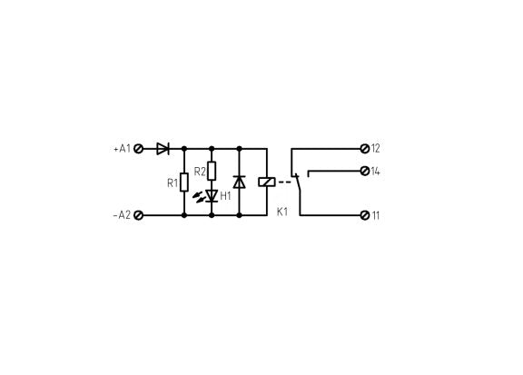
The Wieland FLARE-C1D2 24VDC SPDT Relay Module is a cutting-edge coupling relay designed for precision performance. With a single change-over contact and robust screw clamp terminals, this relay ensures secure connections. It operates on 24 VDC input with a 250 VAC/6A output capacity, featuring a distinctive LED indicator for clear status monitoring. Crafted with high-quality materials and precise engineering, this relay module is ideal for industrial applications requiring reliable switching capabilities.
Ready to Grow Without Cash Flow Constraints?


Product Specifications
Coil Data Maximum Direct Current Dc Input Voltages
22.8 V
Coil Data Minimum Direct Current Dc Input Voltage
25.2 V
Coil Data Nominal Direct Current Dc Input Voltage
24 V
Coil Data Nominal Input Current
7.1 mA
Coil Data Rated Coil Power
170 mW
General Brands
Wieland
General Color Housing
Black
General Connection Type
Screw Terminals
General Degree Of Protection Ip
IP20
General Detachable Clamps
No
General Housing Material
Polycarbonate
General Led Status Indication
Yes (Green)
General Maximum Operating Temperature
60 ºC
General Minimum Operating Temperature
-40 ºC
General Model
FLARE-C1D2-24DC-SPDT-250V6A
General Number Of Change Over Contacts
1
General Screw Terminal Torque
0.4 N·m
Installation Installation
WARNING: Danger to life by electric shock. Do not perform work when voltage is present.This device is installed onto 35mm DIN rails according to EN 60715. Connect wires by plugging them directly into the screw terminals. Then, using a 2.5 mm slotted screwdriver, torque each screw to 0.4 Nm.
Note Note
For Division 2 installations the equipment must be installed in a suitable enclosure.For Zone 2 installations the equipment shall be installed in an enclosure having an ingress protection rating of IP54 or greater according to requirement of C22.2 No. 60079-0, UL 60079-0 and C22.2 No. 60079-7, UL 60079-7 Technical data subject to change
Switching Contact Data Conductor Cross Section Solid
0.25 to 4.0 mm² | 24 to 12 AWG
Switching Contact Data Conductor Cross Section Stranded
0.5 to 2.5 AWG | 22 to 14 mm²
Switching Contact Data Contact Material
AgSnO2
Switching Contact Data Continuous Current
6 A
Switching Contact Data Initial Dielectric Strength Between Conta
1500 Vrms
Switching Contact Data Initial Dielectric Strength Between Open
1000 Vrms
Switching Contact Data Maximum Switching Alternating Current Ac
250 V
Switching Contact Data Maximum Switching Frequency Without Load
0.3 Hz
Switching Contact Data Maximum Switching Frequency With Load
0.1 Hz
Switching Contact Data Mechanical Endurance
5 x 10⁶
Switching Contact Data Minimum Switching Current
100 mA
Switching Contact Data Minimum Switching Direct Current Dc Volta
5 V
Switching Contact Data Switching Power
1500 V·A
Switching Contact Data Release Time
5 ms
Switching Contact Data Response Time
12 ms